Audio Signal Source
This is a lovely project for home constructors keen on building their own test and measurement (T&M) equipment. It makes use of the ICL8038 signal generator chip, manufactured by Intersil. An improved version, made by Exar corp. is available (XR8038A). It can be used to produce three types of waveforms, sine, square and triangle. The frequency, amplitude and duty cycle can be varied, and selection of waveform is done digitally. To further reduce the complexity, a 3-to-1 switch may be used in place of the digital selection circuitry. I made use of the digital selection mechanism because switches available on the market are prone to dirt accumulation and poor contact quality. Besides, the digital method is a lot cooler!
Overview
The circuit shown below can be roughly divided into three parts: the oscillator based around the ICL8038 chip, the selection logic based on the CD4017 and CD4066 and the offset generation and output buffers, based on the LF412. Apologies for the cramped schematic, I had to keep the image size small, and the width under 640 pixels!
The oscillator is a standard 8038-based oscillator circuit, taken from the ICL8038 datasheet. The timing resistor chosen is rather small, to give a wide range of frequencies. This range might be a little too large, making precise frequency setting difficult. In that case, the freqency range may be split into two parts, using two capacitors which can be switched using an SPDT switch. Note that the 8038 is powered from a split supply, not a single supply, to generate a symmetrical waveform without the need for capacitor coupling. Two sine wave adjustment terminals (Pins 1 and 12) are provided, however only one is used. This gives a sinewave distortion of about 1%. To achieve better distortion figures, the circuit shown in Figure 4 of the ICL8038 datasheet may be used. The 8038 is powered from slightly less than +8V to allow the tuning voltage to go above the supply rail. This allows for maximum sweep range (1000:1), however the output waveform tends to be slightly asymmetric because of this. This may be compensated using the offset control R10. R2 controls the duty cycle of the oscillator. R7 acts as the sinewave distortion adjustment. The square wave output of the 8038 is an open-collector output. Hence, a 1k pullup resistor is provided. The sine and triangle outputs are about 5Vpp, while the square wave is 16Vpp. Hence to equalize the different outputs, the square wave is attenuated using a fixed attenuator formed by R6 and R9. A 47k pot may be substituted to make the attenuation level adjustable.
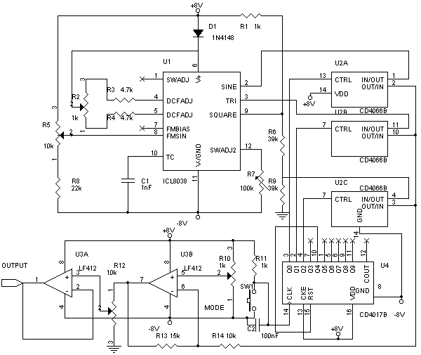
Audio Signal Source schematic
One of the three outputs are then selected using the digital selection circuit. This is based on the CD4066 quad analog bilateral switch and the CD4017 decade counter with fully decoded outputs. I havent used the 4051-series Analog MUXes here because getting a counter to drive this is a bit of a pain. The 4066 essentially acts like four switches under electronic control. The voltages switched must not be above or below the supply voltages. Hence, the 4066 is given both +8 and -8. Now, however, the selection inputs to the 4066 cannot be with reference to ground, and since the selection inputs are driven by the 4017, it too must have a split supply. Hence, note that both chips have ground connected to -8V and not 0V. The 4017 is wired so that it resets itself when the fifth state is selected. The clock to the 4017 comes from a pushbutton switch with a pullup to +8. A 0.1μ capacitor across the switch serves as a contact debouncer. This prevents multiple triggering of the 4017 from a single keypress. Hence, each output is successively chosen when the switch is pressed. The fourth state corresponds to the output being off (DC). On the fifth press, the counter resets itself and selects sine wave again.
The final stage is the offset adjust, amplitude adjust and output driver stage. The offset adjust is an inverting amplifier whose reference pin is not at ground. It is instead attached to a 1k pot's wiper, connected across the supply rails. Hence, when the reference pin is taken off ground, the amplifier introduces a DC shift corresponding to the product of the gain and the reference voltage. The gain of this amplifier is chosen to be about 1.5, to raise the amplitude of the sine and triange waves (but not high enough to cause distortion). The output is passed through an attenuator R12 before going to the output driver voltage follower. This stage uses an LF412 opamp, since the risetime of the square wave imposes a high slew rate on the opamp. Cheaper opamps such as the LM358 have poor slew rates compared to the LF412. Also, the LF412 has a robust output stage. A mistake in this design is putting the attenuator after the stage introducing a voltage offset. This means that even the offset is attenuated along with the signal... not desireable behaviour. The solution would either require a pot with a high resistance (100k or more) in place of the 10k unit here, connected before the offset-introducing inverting amplifier U3B. No pot is required between U3B and U3A.
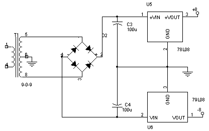
Audio Signal Source Power Supply
The power supply is a regular split-supply design based on a 78L08 and 79L08 linear regulators. I made use of a 9-0-9 transformer, which was a bit risky (very low headroom voltage for the regulators), but then my dealer didnt have a stock of 12-0-12 transformers. The output of the transformer is rectified and smoothed using 100μF capactors. The float-voltage measured here for the 9-0-9 transformer was +/- 13V. The unregulated DC is regulated by the 78L08 and 79L08 to give the regulated supply rails for the circuit.
Construction
Again, the usual breadboard/veroboard. I used Relimate connectors for all the connections to and from the board. As a retrofit, I also added a connector to make available the +/- 8V rails to outside projects, since I do not own a bench split supply. The whole works was shoved into a small plastic chocolate box (!!!), but I haven't got down to drilling holes for the pots, switch, etc. etc. Performance was quite good, I measured frequencies up to 60kHz, with a rather clean looking sine wave. The square wave was attenuated too much, but that was OK by me. The rise time for the square wave was very good. As a test, replacing the LF412 with an LM358 resulted in very poor square wave output (it almost looked like a sine!), and other waveforms seemed to have crossover distortion (*shrug*... crossover distortion in an opamp!!!) Amplitude could be adjusted from 0V to about 7Vpp for all waveforms. Contact bounce was still a bit of a problem for the counter, sometimes the counter moved two places rather than one. A higher value capacitor will help a bit. I attached three LEDs through 1k resistors to each of the three used outputs of the 4017 to indicate which waveform is selected. This wasnt included in the schematic due to space constraints.
It would be wise to go through the excellently written
"Everything You Always Wanted to Know About the ICL8038" (AN013.1) by Intersil. It is available at
Intersil's website, along with the ICL8038 datasheet.
Improvements
As I mentioned, move the attenuator to before the offset stage. I'm planning to make a frequency synthesizer based on a similar circuit with a PLL, using the 8038 as the VCO. It should be under computer control or use a microcontroller to form a stand-alone instrument.
Disclaimer
These circuits are provided for your own study only. They all deal with electricity and electronics, a sufficient knowledge of both is assumed. I will not take any responsibility for any personal injury or damage to property arising from use or abuse of the information provided on these pages.