Digital Voice Recorder
This project was completed for my 6th semester project lab, along with my batchmates Gautham Krishnamurthy and Venkatesh HB. It is a simple device that emulates a dictaphone, and stores the voice digitally.
Overview
Block Diagram
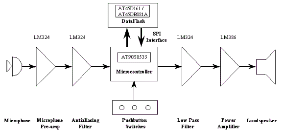
The heart of the Digital Voice Recorder (DVR) is an Atmel AT90S8535 microcontroller. It is a powerful RISC 8-bit microcontroller, with 8kB internal FLASH program memory, 512 bytes EEPROM and 512 bytes of SRAM. It's RISC CPU core can execute almost 1 instruction per cycle. The core is complemented with a rich set of peripherals, including I/O ports, timers, PWM, A/D converters, etc. Details can be found at
Atmel's Website. A 16 Megabit data-storage FLASH chip (AT45D161) is attached to the MCU through a serial interface (SPI). This stores the sampled data from the MCU, and also sends back stored data to the MCU. Four pushbutton switches and four LEDs form the user interface. These are connected to the MCU's I/O ports. The audio is picked up by a condenser microphone, and amplified by an op-amp based amplifier. It is filtered and passed to the MCU's A/D converter, which samples the audio at a rate of 8kHz. The 10-bit samples are scaled down to 8 bits before storage. During playback, the samples stored in the FLASH chip are sent to the MCU's PWM module, which produces a 15kHz PWM signal whose pulsewidth is proportional to the amplitude of the sample. This is filtered and amplified, and is passed to a loudspeaker.
Analog circuitry
The Analog circuitry in this project contains a microphone pre-amplifier, an anti-aliasing filter, a postfilter and a power-amplifier. The condenser microphone is biased using a variable resistor and the DC component blocked by a capacitor. The microphone amplifier and filter is implemented using an inverting op-amp amplifier configured for a high gain. The gain is, again, adjustable. The filter is a simple single-stage RC filter. The capacitor in the feedback loop introduces a rolloff at high frequencies, giving better stability since the gain is very high.
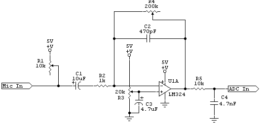
Input Amplifier
The output filter is made using a 5th order Chebyshev active filter. It is configured as two stagger-tuned 2nd order filters, and a single first order filter. The cutoff frequency is set at 3.9kHz. This ensures that almost the entire audio spectrum is passed through, but the PWM carier (at 15kHz) is cut off. The filter is designed using FilterWiz Pro software.
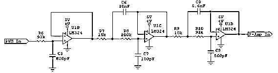
Output Filter
The power amplifier is a low-power design, based on the LM386 monolithic power amplifier chip from National Semiconductor. This chip is capable of delivering 1W of output power. It is a high-efficiency chip, which makes it ideal for battery operated applications. A volume control is included. The output side contains a Zobel network to cancel the effects of the speaker impedance.
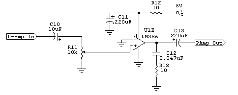
Power Amplifier
Digital circuitry
The digital circuitry consists of the MCU and DataFlash interface. The MCU I/O ports are shown connected to the LEDs and switches of the user interface. One port (PORT B) is used to communicate with the DataFlash. PORTA, which also serves as the A/D converter inputs, is connected to the microphone pre-amplifier. An 8 Mhz crystal is connected to the MCU to provide the system clock.
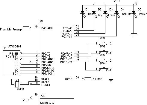
Digital Circuitry
Software
The software that runs on the 8535 MCU is written in C. It is designed for the
ImageCraft C compiler for the AVR. It is interrupt driven, and makes use of the MCU's inbuilt timers to provide the sampling rate clock. Thus, a stable sampling frequency is produced. All operation of the software is based on this interrupt. Recording and playback are implemented as seperate functions. The code is well commented, and is more or less self-explanatory.
Download the code:
dvr.zipImprovements
This device can be improved by using compression techniques to compress the audio before storing into the dataflash chip. This would allow the device to store more than 4 minutes of audio on a 16 Megabit FLASH chip.
Disclaimer
These circuits are provided for your own study only. They all deal with electricity and electronics, a sufficient knowledge of both is assumed. I will not take any responsibility for any personal injury or damage to property arising from use or abuse of the information provided on these pages.