Digital Voltmeter
This project is a good one for experimenters who are experienced at interfacing external circuits to a PC. It's a bit expensive because it makes use of a Parallel interface card, which may be difficult to get for some. In 2001, they cost Rs. 950 each.
Overview
The project can be broken into three parts, the attenuators, the A/D converter and the interface card. The attenuator section divides the input voltage by a programmable amount. The A/D converter converts the divided voltage into a range of codes ranging from 0 to 255. The interface card allows the PC to read the data from the A/D converter and to set the values of the attenuator.
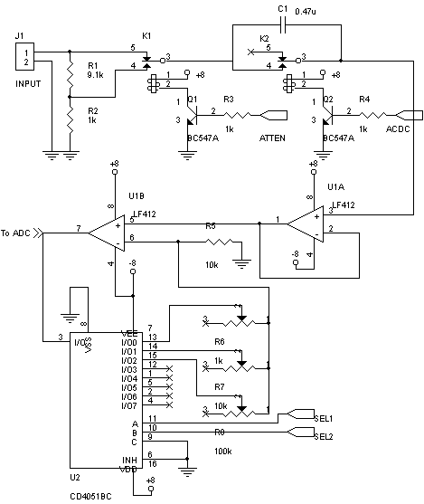
Digital Voltmeter - Input Attenuator
The input attenuator has four main parts: the ÷10 attenuator, the AC/DC selector, a buffer and a programmable attenuator (×10, ×1 and ÷10) The ÷10 attenuator is used to measure high voltages (>10V) since these will damage the rest of the input stages if passed directly. For extra protection, two back-to-back 9.1V zener diodes can be connected to ground after the divider. Note that I have used rather low values of resistors (9.1k and 1k), which gives a ridiculously low input impedance of 10k!!! Since my DVM was experimental, this is OK. However, you should do something a bit more smart and use higher value resistors with the same ratio. The attenuation can be bypassed using a relay, which is under the control of the PC. The AC/DC selector uses a 0.47uF nonpolarized capacitor to act as a DC blocking capacitor. Again, the capacitor can be bypassed using a relay under the control of the host PC. The buffer amplifier is used to provide some isolation from the rest of the DVM. The last part is a programmable gain amplifier, based on an opamp (½LF412) and a 4051 analog multiplexer. The analog MUX is used to select different feedback resistors into the feedback loop. The feedback resistors chosen are pots, allowing you to calibrate each range seperately. Please note that the 4051 must have a dual supply (Vee ≠ ground) because it handles bipolar analog voltages.
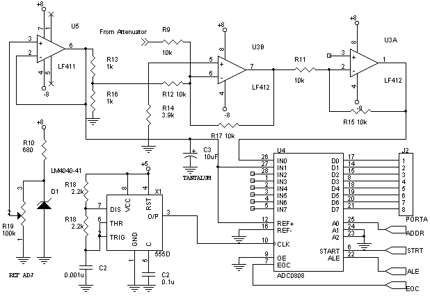
Digital Voltmeter - ADC and Reference
This part of the circuit supplies an offset to the attenuated voltage, making it unipolar. This acts as a level shifter. We cannot use something like a clamper, since clampers work only for AC voltages. The reference voltage is generated by an LM4040-41 reference voltage IC from National Semiconductor. The LM4040-41 produces a very stable voltage of 4.096V. This voltage is divided by the 100k pot (marked "Ref Adj"), and buffered by the LF411 opamp. The pot is adjusted with a calibrated DMM connected to the output of the LF411 amplifier, so that the DMM reads 2.56V exactly. This is filtered by a 10uF tantalum bead capacitor (for a good HF response, a ceramic capacitor may also be used). The 2.56V reference is also divided by a potential divider formed from 1k resistors. This gives a 1.28V reference, which is added to the input voltage using a summing amplifier. This amplifier inverts the signal, so an inverting amplifier is used to invert the signal once more. This voltage is now the input voltage scaled down to a +/- 1.28V signal and added with a 1.28V offset voltage. This is then fed to one of the ADC's inputs. In order for the software to compensate for any potential changes in the added offset voltage, another of the ADC's inputs are tied to the Vref/2 point.
The software running on the PC performs a measurement cycle by first setting the AC/DC selection relay, attenuator relay and programmable attenuator to the proper values. Now, the ADDR pin of the output port is made high, to select Analog input 1 (the offset voltage) and the STRT pin is pulsed. The software enters an idle loop, where it waits for EOC to become high. Once the ADC finishes the conversion, EOC goes high, and the PC reads the 8-bit conversion result. This number is then scaled to the appropriate voltage and displayed (in case of DC). In addition, for DC, averaging may be done, along with min/max calculations. In the case of AC, the software identifies the start and end of a complete cycle of the AC voltage, and does an RMS calculation as follows:
√Σ xi2
A lot of possible calculations may be applied to the signal recieved from the ADC. It may be logged to a file, plotted as a graph, etc. Since all the required calculations are done in software, development is easy.
Disclaimer
These circuits are provided for your own study only. They all deal with electricity and electronics, a sufficient knowledge of both is assumed. I will not take any responsibility for any personal injury or damage to property arising from use or abuse of the information provided on these pages.