Audio Level Meter
This is a nice project to display the level of an input audio signal. It makes use of the National Semiconductor LM3916 bargraph/LED driver chip. This chip is a complete LED VU meter driver chip. It is similar to the LM3914 linear bargraph driver and the LM3915 logarithmic bargraph driver. It's LEDs correspond to the standard VU scale from -20dB to +3dB, excluding -2dB. This project provides for only a mono display. It can be modified for a stereo display as well.
Overview
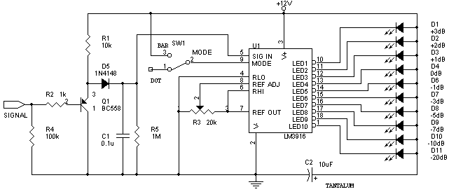
The circuit is quite simple, it is more or less the same as that given in the datasheets of the chip. The LM3916 is fully configurable through the use of external components. In the circuit shown, the potentiometer connected to pins 6, 7 and 8 set the reference for +3dB signal. It should be adjusted so that when a 0dB audio signal is fed into the input, the 0dB LED should just light. In addition to the LM3916, a peak detector circuit is built around the BC558 transistor. It's purpose is to make the level meter a peak-reading one. This is accomplished by rectifying the signal using a 1N4148 signal diode and then filtering using a capacitor. This is essentially a clamper circuit. The 1M resistor acts as a bleeder resistor. Hence, the value of this and the clamp capacitor determines the hold time of the meter. It is meant to provide a fast attack and slow decay time. Experimenters may want to use a 1M pot instead, to allow the decay time to be fixed. A simple diode clamp is not used, since the diode's 0.6V forward drop will cause errors. The Vbe drop of the transistor, however, compensates for this drop. Please note that the input may be DC coupled, but it's wise to use a coupling capacitor to remove any possible offsets present (due to improperly balanced opamps in previous stages.)
Audio Level Meter
The LM3916 VU-meter chip can drive the LEDs in either dot mode or bar mode, which is selected by connecting pin 9 to Vcc (Bar mode) or leaving it open (Dot mode). In bar mode, the LED power consumption is quite high, and this might cause large currents to flow through the GND pin of the chip. To avoid any problems that may occur, use a large supply decoupling capacitor at the power entry of the board, and a 0.1μF decoupling capacitor close to the chip. Keep all ground leads short and terminate them at a single point.
The LM3916 may be substituted by the LM3915, but the range of the display will be rather limited, and will not correspond to the standard VU meter markings. An LM3914 may be used only if a logarithmic amplifier is placed before driving the circuit. As with any device, it is a good idea to read the LM3916 datasheets (available at
National Semiconductor's website) before constructing this circuit.
Construction
Construction was done, again, on a veroboard. I made use of a tantalum capacitor mounted close to the LEDs (gotcha! It's not close to the IC for once), this reduces the chances of LED switching currents causing volage drops that lead to errors. It may be helpful to use a 0.1μF decoupling capacitor mounted close to the LM3916. For the LEDs, I bought a small packaged bargraph display, manufactured by Izra Electonics (they're available at Vishal Electronics, SP Road, Bangalore for about Rs. 35. They might not know what you're talking about, try and explain to them what you want.) I found that they have a nice, bright display and none of the physical variations associated with individual LEDs mounted in a line. In addition, all segments have a uniform brightness. Similar units are also available from Kwality Photonics, altough I have not actually bought or tested them. The audio is coupled in through a stereo headphone socket. The LED mode is chosen using a jumper salvaged from an old hard disk.
Disclaimer
These circuits are provided for your own study only. They all deal with electricity and electronics, a sufficient knowledge of both is assumed. I will not take any responsibility for any personal injury or damage to property arising from use or abuse of the information provided on these pages.