Four-Hour Timer
 Warning: This project deals with AC mains voltage. If you are a beginner, PLEASE SEEK ASSISTANCE!
|
Here is a nice easy-to-do project for constructors: it's a device that will switch an attached appliance on when reset, and automatically turn it off four hours later. I was asked to design and build it for my friend Uday's dad, and the intended load was a neon signboard. It's actually quite basic, and can be easily extended to include lots of other features.
Overview
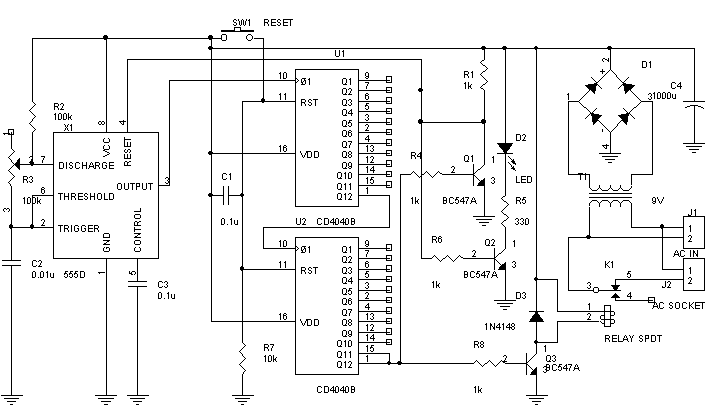
This circuit consists of a clock generator based on a 555 timer. It produces a clock of approximately 600Hz, which is then divided down by two divide-by-4096 counters based on a pair of 12-stage asynchronous counters (CD4040). The resulting waveform has a frequency of 36μHz, corresponding to a time period of 27962.02 sconds. This is about 7 hours, 46 minutes. The total time for which the waveform stays low is then 3 hours 53 minutes. The reason for using two counters is that if only one were used, we'd have to generate a 6Hz waveform, meaning the use of an electrolytic capacitor in the timer. This gives problems of temperature dependence and inaccuracy. Also, a CD4040 costs just Rs. 12.
Four Hour Timer
The circuit operation is straightforward. On power up, the capacitor C1 charges up, causing the counters to reset. After a short time, the reset condition is automatically removed. This ensures that on power up, the devices are in a known state. In case the devices do not reset, then try replacing C1 with a higher value (1μF). After being reset, all the outputs of the 4040 ICs are low. Hence, Q1 and Q3 are off. Q2 is on, hence the LED indicates that the device attached is switched on.
The counters count up, and when the last bit of the second counter goes high, the transistors Q1 and Q3 switch on, and Q2 switches off. Hence, the RESET pin of the 555 is pulled low, inhibiting it from counting. Hence the counters stop, and the device will not switch on again after another 4 hours. The LED goes off, indicating that the appliance attached is switched off.
Construction
The circuit was built on a veroboard, nothing critical. Instead of using a packaged diode bridge, I used four 1N4007 diodes, it's cheaper. The filtered voltage was seen to fluctuate sharply as the relay switched on and off. However, it did not cause false triggering of any sort. The circuit's inputs and outputs were connected through a Relimate connector for reliability. Connections to the transformer, relay, LED and switch were through the connector. The circuit board was attached to the case using a single bolt. All wiring was done from the component side, giving a slightly messy look, but ensuring reliability (this being the time I did not know of any better
circuit construction methods.
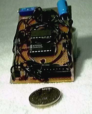
The completed circuit board
The casing was bought at a rather steep price (Rs. 55) for a box without a front or a back! I used the plastic from a discarded oil can to make a front panel and a rear panel. The front panel was drilled out, and a sheet of paper pasted onto it. A transparency with the desired decal was printed and pasted on top of the paper. The LEDs and switches were then mounted using silicone glue. Holes were drilled in the casing to mount the relay, circuit board and transformer. I used a small hacksaw blade to cut out a hole in which the AC socket was mounted. The entire apparatus was then assembled, and all bare wires insulated with heat-shrink tubing. The final result...
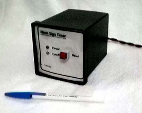
External view. Note the Device and Power LEDs, and
the reset switch.
After assembly, I varied the 100k pot until the 555 produced a 585Hz wave (calculate ((1/8Hours in seconds)/(4096 * 4096)))
Improvements: The time delay can be modified in two ways: one by adjusting the 100k pot, the other by choosing a different output from the counter ICs. In fact, the pot can even be made a front panel control. I didn't do this because it was not a part of the original specification.
Disclaimer
These circuits are provided for your own study only. They all deal with electricity and electronics, a sufficient knowledge of both is assumed. I will not take any responsibility for any personal injury or damage to property arising from use or abuse of the information provided on these pages.