Stepper Motor Controller
This is a simple project to allow a stepper motor to be controlled from an IBM-compatible PC's parallel port. The parallel port is an excellent interfacing mechanism, allowing all sorts of devices to be connected to and controlled by a PC. Please note, however, that it can be easily damaged, so exercise caution while using the parallel port to perform any sort of I/O operations. Do not hold me responsible for frying the insides of your computer due to your mistakes! If you're not sure of what you're doing, get help before proceeding.
Overview
The parallel port has several I/O lines, which can be partitioned into two, the data lines and the control lines. The data lines are unidirectional (OK, OK, stop howling, I know about ECP/EPP, I'm trying to keep it simple here!) and data flows out from the PC. These are used in the circuit.
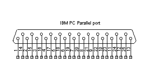
The IBM PC Parallel Port
Pin 1 can be identified by looking at the connector plastic. Good quality connectors have Pin 1 marked in some way. Usually, all pins are labelled. The pin assignments are as follows:
| Pin No. | Pin Name | Direction | Description |
| 1 | Strobe | INOUT | Pulled low by PC for each transfer done |
| 2-9 | D0-D7 | OUT | The eight Data bits. |
| 10 | Ack | IN | Pulled low by the device after getting byte |
| 11 | Busy | IN | Device indicates it is busy by pulling high |
| 12 | Paper Out | IN | For printers |
| 13 | Select | IN | Device indicates it is ready by pulling high |
| 14 | Autofeed | INOUT | ? |
| 15 | Error | IN | Indicates an error |
| 16 | Initialize | INOUT | ? |
| 17 | Select-In | INOUT | ? |
| 18-25 | Ground | GND | Some pins are power ground, some signal and some chassis. |
Pin Assignments
The stepper motor is obtained from an old 5.25" disk drive, model no FD-55GFR from Teac. This was bought for Rs. 200 from a local market (Thanks, Uday!) I extracted a small stepper motor, with a five-pin input, which had me stumped for a while. Most textbooks talk about bifilar-wound stepper motors, which have 6-pin input. Some also describe 4-pin steppers, which omit the center tap (and require bipolar drive circuitry). Lots of searching on the net gave me the answer: the motor is similar to 6-pin steppers, but have the center-tap of the two windings connected together. Hence, it's not possible to drive these using bipolar methods, reducing the mechanical power output. For more details on stepper motors, try visiting HowStuffWorks.com and searching for stepper motors.
Extracting the motor from the drive is easy, only a few screws need to be removed. The shaft has a thin metal tape screwed on to it, be careful not to cut your hands while removing it. First, verify that the motor works. The easiest way to do this is to short together all the wires coming out, and turn the shaft. You should feel a strong resistance. You may also use a multimeter to check the windings for continuity. The common pin is marked with a stripe. The stepper motor pins can be then be identified by the following process:
- Connect a 12V supply to the common pin (marked by a stripe on the wire) and the next pin you see. The motor should turn by a small amount. Label this Pin 1.
- Leaving these two wires in place, connect the other pins successively to the 12V supply. Note that two of the pins make the motor turn by small amounts, in opposite directions. Label one of them Pin 2, the other as Pin 4.
- The last remaining pin should cause no movement. Label this Pin 3.
The driver makes use of the ULN2003 driver IC, which contains an array of 7 power-darlingtons, each capable of driving 500mA of current. The device has base resistors, allowing direct connection to any common logic family. All the emitters are tied together and brought out to a seperate terminal. Output protection diodes are included, hence the device can drive inductive loads with minimum extra components. Only four of these darlingtons are actually used here.
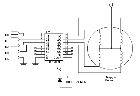
Stepper Motor Driver
Please note that the first pin (identified in the procedure shown above) is connected to D0 of the parallel port (through the ULN2003, of course). Each successive pin of the stepper motor is connected to successive data lines on the parallel port. If this order is not correct, the motor will not rotate, but will wiggle around from side to side. The clamp circuit shown does not connect the clamp directly to the supply voltage. Instead, it uses a zener diode. This ensures that the decaying current in the coils are not abruptly cut off, which produces a lot of heat. The software written for this project is simple, it involves setting the bits on the port on and off in a specific sequence. The sequence is given below:
| Step No. | D0 | D1 | D2 | D3 |
| 1 | 1 | 0 | 0 | 0 |
| 2 | 0 | 1 | 0 | 0 |
| 3 | 0 | 0 | 1 | 0 |
| 4 | 0 | 0 | 0 | 1 |
Full Step
| Step No. | D0 | D1 | D2 | D3 |
| 1 | 1 | 0 | 0 | 0 |
| 2 | 1 | 1 | 0 | 0 |
| 3 | 0 | 1 | 0 | 0 |
| 4 | 0 | 1 | 1 | 0 |
| 5 | 0 | 0 | 1 | 0 |
| 6 | 0 | 0 | 1 | 1 |
| 7 | 0 | 0 | 0 | 1 |
| 8 | 1 | 0 | 0 | 1 |
Half Step
The difference between half step and full step is that for the same step rate, half-step gives you half the speed, twice the resolution, and roughly twice the power consumption. It also gives you twice the torque. To reverse the direction of the motor, send the sequence in reverse order. A short example program for TurboC, running in MSDOS, drives the motor in full-step, forward direction.
#include <conio.h>


void main () {

 unsigned char v = 0x11;


 while (!kbhit ()) {

  	delay (10);

  	outportb (0x378, v);

  	asm {

    mov al, v

    rol al, 1

    mov v, al

  }

 }

}
A more complete program is
this one, written in MFC, with a nice GUI you can play with. It can drive half step, full step, forward and reverse, with a single-step and auto-step capability. You can also turn on and off individual windings.
Improvements: Not much. I wanted to try to figure out ways to control the motor, that's why I did this. My ultimate goal is to use a microcontroller to do this work. Stay tuned...
Disclaimer
These circuits are provided for your own study only. They all deal with electricity and electronics, a sufficient knowledge of both is assumed. I will not take any responsibility for any personal injury or damage to property arising from use or abuse of the information provided on these pages.