Dynamic Noise Reduction
This project is a noise reduction circuit based on the National Semiconductor LM1894 Dynamic Noise Reduction (DNR™) IC. This chip implements a non-complementary noise reduction scheme, which means that the original program material needn't have been specially recorded. This is done using a low-pass filter whose cutoff frequency can be voltage-controlled. The cutoff frequency is proportional to the peak level of the input signal. Full details of circuit operation can be obtained from the LM1894 datasheet, available at the
National Semiconductor Website. It is particularly useful in removing tape noise from the output of a cassette deck, improving the SNR by as much as 10dB (ARM weighted).
Overview
This circuit is from the LM1894 Datasheet's application circuit. Its operation can be easily understood by looking at the block diagram of the device. It consists of two seperate lowpass filter units whose cutoff frequency is determined by a control voltage. The stereo input signal is summed to form a mono signal. This is fed to a peak detector and smoothing capacitor, which produces a voltage corresponding to the peak amplitude of the input signal. This is then used to adjust the cutoff frequency of the lowpass filters. The circuit exploits the psychoacoustic property that a signal in a single sub-band can be masked by noise of equal power in the same sub-band and vice versa. Hence, as the audio amplitude decreases, the higher frequency components are attenuated, thus lowering the noise power (which is proportional to bandwidth) and at the same time, removing the most objectionable portion of the noise signal (namely, the higher frequency parts).
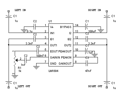
Dynamic Noise Reduction Circuit
I thought I'll be lazy enough to just swipe the circuit from the datasheet itself, however Acrobat's *&%$@! antialiasing saw to it that I cant do that... and sorry about the component names. Anyway, the circuit is mostly capacitors used for coupling and bypass. The major components are all within the LM1894 itself. The only adjustment to be made is the 1k pot shown between pins 5 and 6. This pot sets the threshold which the signal must fall below for the DNR circuit to start acting. The procedure for adjusting this is outlined in the LM1894's datasheets, it involves playing a blank, but biased, tape and adjusting the pot until the noise is cancelled. By biased, I mean the tape must be recorded, but not have any program material. Hence, you cannot use a tape that that has just been removed from the shrinkwrap. This pot must be re-adjusted for changes in supply voltage, tape bias (Normal/CrO2/Metal) and any additional noise reduction, such as Dolby. Please note that this circuit must be used
before any volume/tone controls, and will work with an input amplitude such that the voltage does not exceed V
cc - 1V. National Semiconductor has published excellent documentation regarding this chip in a series of application notes:
- Audio Noise Reduction and Masking (AN-384)
- A Noncomplementary Audio Noise Reduction System (AN-386)
- DNR Applications of the LM1894 (AN-390)
These make very good reading, and are highly recommended. Visit
National's website for these and other application notes and datasheets.
I constructed this circuit on a veroboard, with no special components. All capacitors were either electrolytic or ceramic disc. I'm no audiophile, but the resulting circuit sounded EXCELLENT!!! With correct adjustment of the pot, tape noise can be cut out almost totally (for normal listening volumes) without affecting the high-frequency components of the program material. Inputs and outputs were provided using Stereo minijack sockets, and power supply was through a small 12Vdc Wall-power supply.
Improvements: The appnotes list various methods of introducing switching systems into the LM1894 to allow the user to choose the type of tape in use, and to allow the circuit to be used for noise-cancellation for FM Radio broadcasts.
Disclaimer
DNR™ is a registered trademark of National Semiconductor corp. A license is required for commercial use of the LM1894.
These circuits are provided for your own study only. They all deal with electricity and electronics, a sufficient knowledge of both is assumed. I will not take any responsibility for any personal injury or damage to property arising from use or abuse of the information provided on these pages.